Homemade footmouse, details
This page contains the details of my footmouse.
See the footmouse-page
for a global explanation of my homemade footmouse.
From idea to design
There were two problems. The first is which motion
you would have make, and the second is how to send that to
the computer. I have thought of many things, such as:
• Transferring the motion with waxed floss wire to
a mechanical mouse. Waxed floss wire does not skid because of the wax.
• Use both feet to control the cursor, with switches under the toes.
• Using the knees.
• Using the joystick interface. That is however very inaccurate.
• Setting the speed of the cursor instead of the position.
That is slowly.
• etc.
But those are not good ideas.
Next, I decided to think about the best motion for the feet,
and examine how its moves and twists and see where the
articulation points would be.
So I came up with a pedal like a gas pedal, and added
a left-right motion. If I would use the same pedal
for the left foot, I could serve four mouse buttons.
With this construction it is not possible the wobble the
feet to the left and right (like on ice skates).
In practice, that proved to be very good, because it gives
some kind of stability, while the pedals still can move
freely around.
It appeared that the front of the foot (at the toes)
almost scans a virtual mini-screen. So the next step was to add
the optical part of an optical mouse at that place.
It seemed to me that the position of the mouse cursor
is best controlled by the right foot.
I am right-handed, and it seems that I can make
more precise movements with my right foot. Everyone who
is able to drive a car has also already more precise
control over the right foot (gas pedal) than the left foot
(clutch).
If the front of the foot goes down, then the cursor on the
screen also goes down. That is more logically and more natural
than the other way around.
The left foot has four mouse buttons (micro-switches). After some time I came
up with this order:
The first mouse button is selected if the left foot goes down,
because that is the most simple motion a foot can make.
The second mouse button is selected if the left foot goes up.
The third mouse button is clicked if the left foot twists to
the outside. This motion is simpler than
to twist inside. To twist inside becomes thus the fourth mouse button.
A rubber band was necessary for the left pedal,
to keep it in the middle while no buttons are clicked.
2003
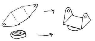
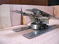
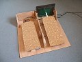
Construction
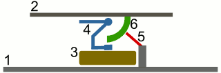
Here is a sketch of the right pedal.
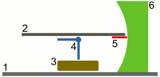
1 = base plate
2 = pedal
3 = ball bearing
4 = hinge
5 = optical part of a mouse
6 = concave shape
A part of the hinge is cut off, so it fits in the ballbearing.
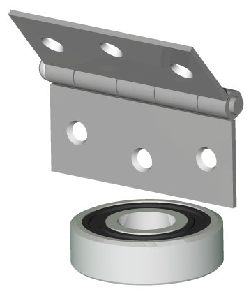
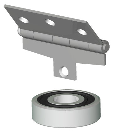
The ball bearing will be damaged by the welding, but the ball bearing does not need to rotate a lot.
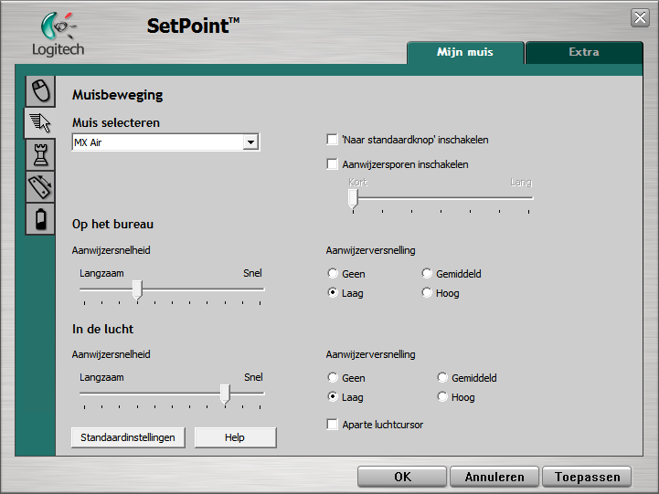
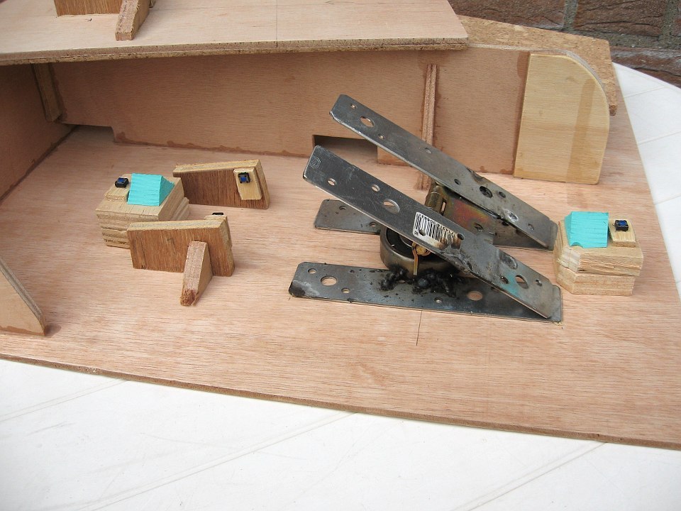
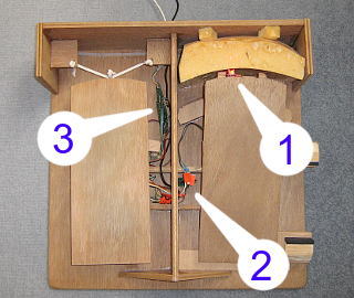
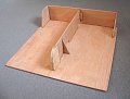
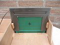
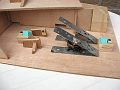
Top view:
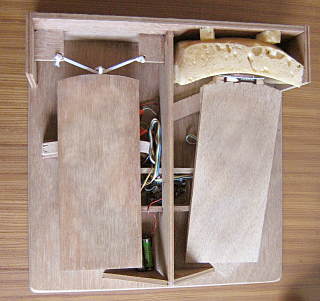
In the box in the middle is the main circuit board of the mouse.
In front of the right pedal is the optical circuit board of the mouse.
I used white glue for wood (water based) for the wood, because that can
be hit apart with a hammer. So I can easily make changes.
For the part that needed to be fixed I used construction adhesive.
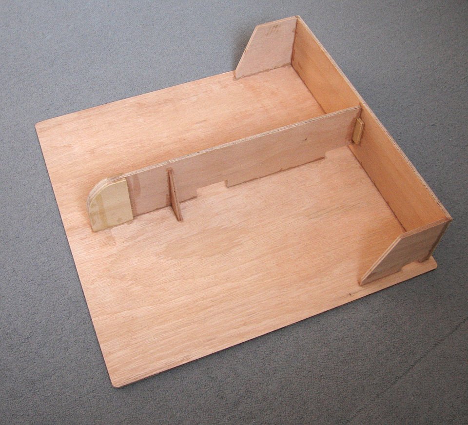
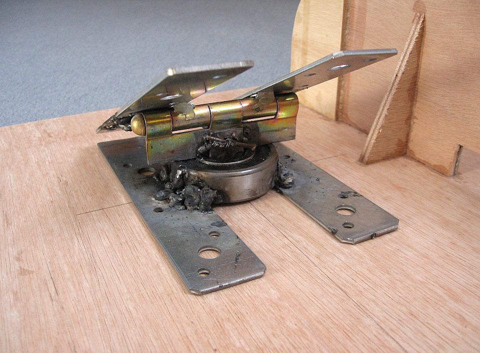
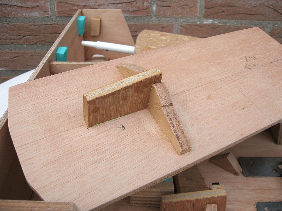
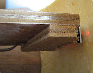
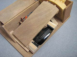
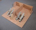
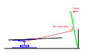
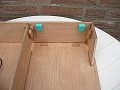
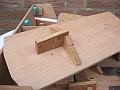
This is a side view of the footmouse:
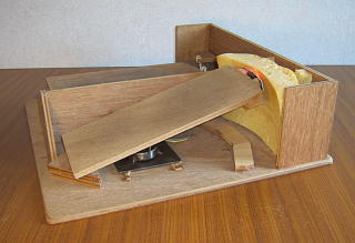
If the pedal tilts fully forward or backward, it is stopped by wooden blocks,
which are glued to the base plate. This reduces the maximum angle of the pedal,
and to protect the optical part. The vertical plank in the middle takes care
of the maximum left and right rotation.
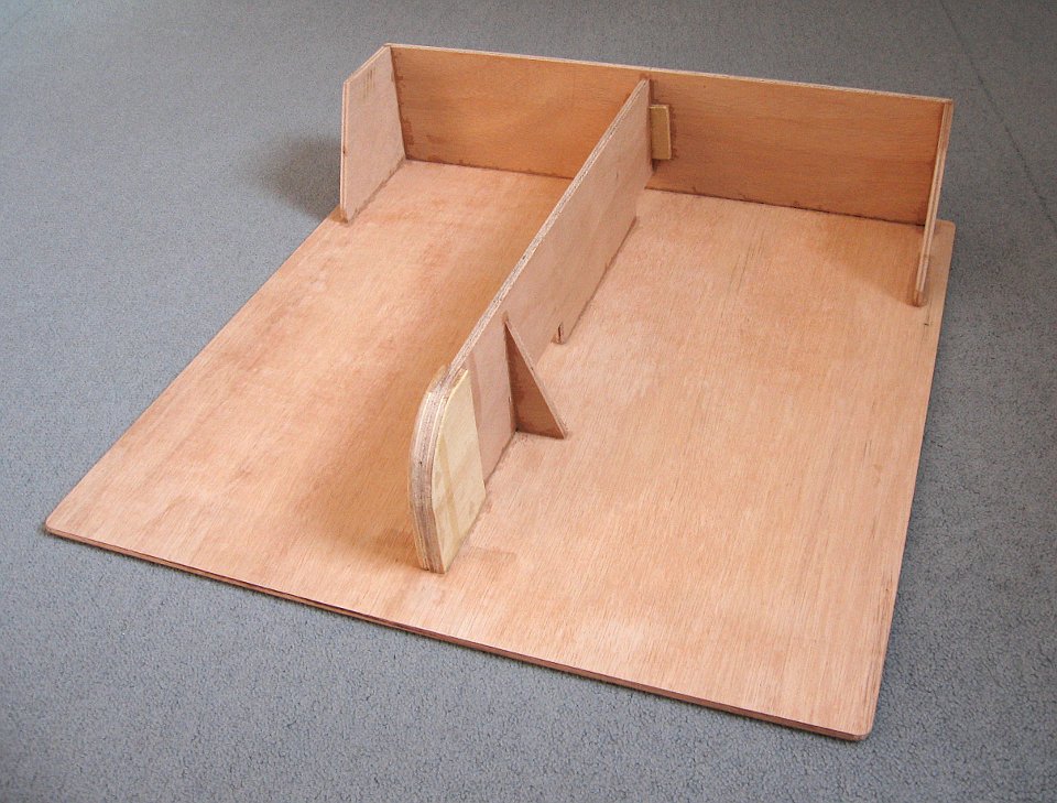
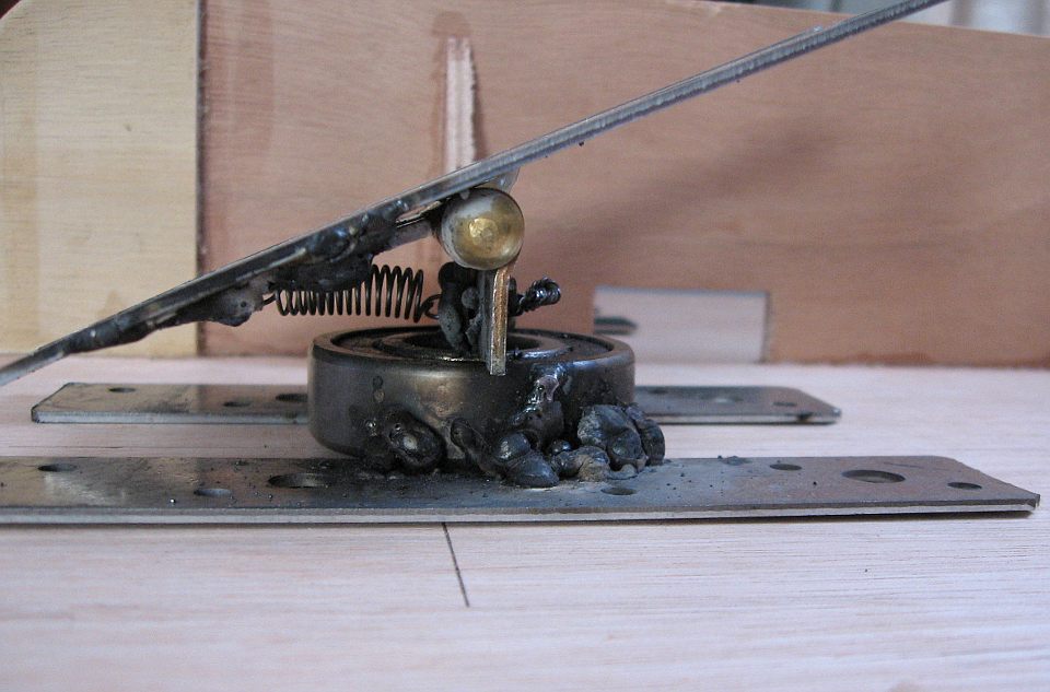
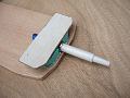
This is the side view of the right pedal:
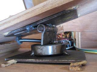
The iron top plate en bottom plate are 2 mm thick.
The metal of the hinge is also 2 mm thick.
The ballbearing 52 mm diameter and 15 mm high.
The iron plates have to be that thick, or they will deform by the welding.
The ballbearing is large, because it will get some damage by the welding.
The ballbearing is welded a little above the base plate, so it still can freely rotate
A spring keeps the pedal tilted backward.
That makes it easier to place my foot on it.
On top of the hinge, I glued some spacers (just a few rings),
so the vertical part of the hinge does not touch the top plate.
This way the hinge turns(tilts) as smooth as possible.
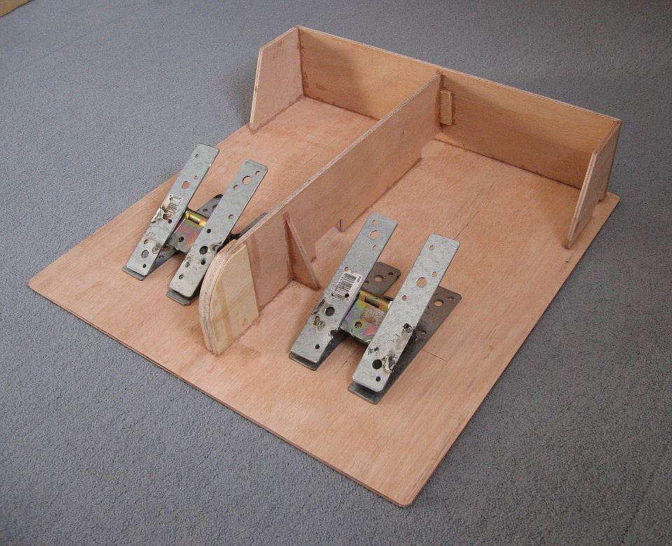
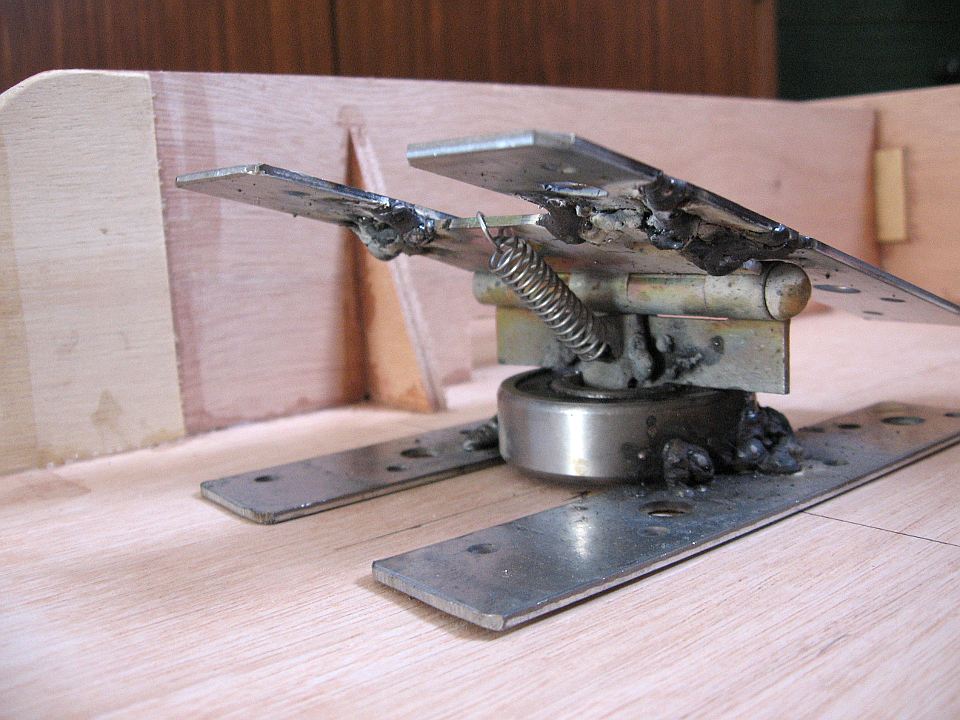
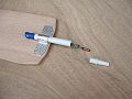
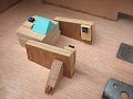
This is a side view of the left pedal:
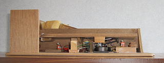
The pedal has the same construction. It has also a spring, but that has no function.
The switch on the right in the photo is placed higher than the left switch.
I have done that, so I don't have to tilt backward so much, and that is better.
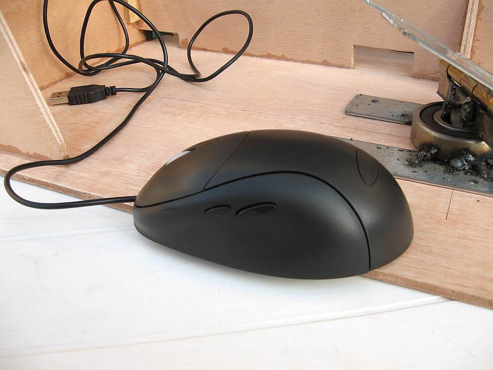
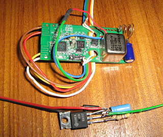
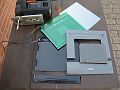
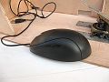
This is the "Logitech Cordless MouseMan Wheel Optical".
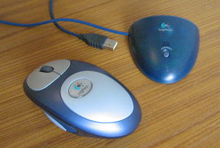
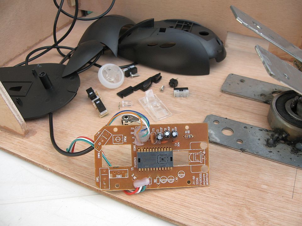
This mouse contains three circuit boards.
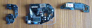
The circuit board on the left is for the scrollwheel. I don't use that. The circuit board in the middle is the main circuit board. The circuit board on the right is the optical part. Between the main circuit board en the optical part I soldered a few wires.
On the main circuit board I soldered wires to the switches underneath the left pedal.
And I soldered two wires to a battery holder for two AA batteries.
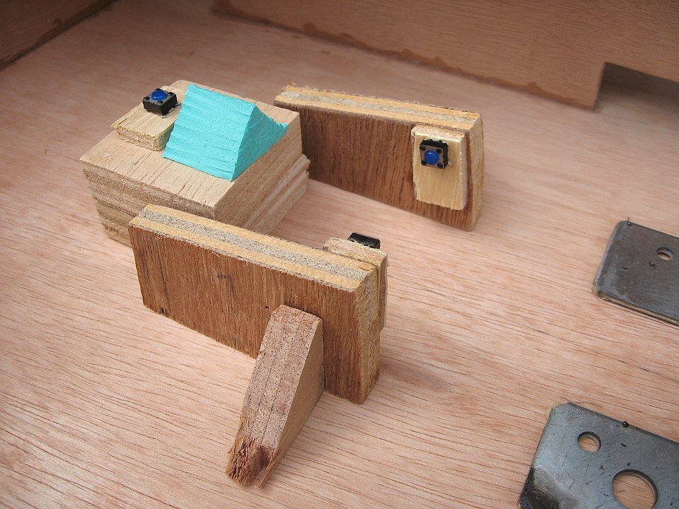
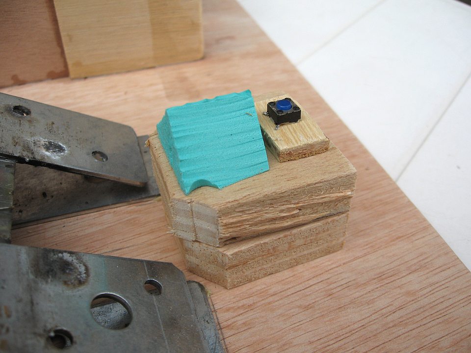
This photo shows some shapes of construction foam.
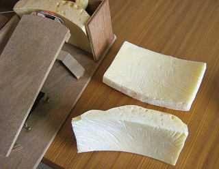
These shapes were hard to make.
To get the right concave shape, I used a Skippy ball, on which I put the construction foam.
I covered the Skippy ball with plastic wrap (cling-film).
These are the boxes of the ballbearings.
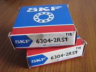
These ballbearings costs between 5 and 20 euros.
I use these batteries:
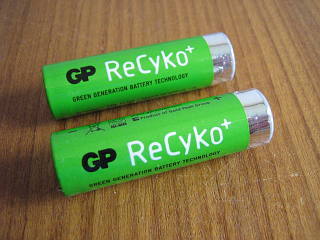
They are NiMH rechargeable batteries with low leak current. These one last the longest, they are two AA batteries of the brand ReCyko+ from GP.
Improvements
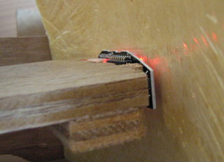
The optical part of an optical mouse scans normally the
table where the mouse lies on. With my footmouse it
scans a concave shape, which I made of construction foam (PU-foam).
That concave shape is very hard to make. It is the opposite
of a sphere within 2mm (less than 1/10 of an inch) deviation.
This construction is therefore not ready to go on the market.
However, that concave shape can be replaced by a sphere shape
which is placed under the pedal. The sphere shape is connected
to the pedal en turns around along with the pedal.
The optical part of the mouse could then be fixed on the base plate.
This way everything can be placed under the two pedals, and the
front part can be omitted, so the only thing you see will
be two pedals.
Below is a sketch. The pedals can't tilt more than
40°, but probable 30° is already sufficient.
1 = base plate
2 = pedal
3 = ball bearing
4 = hinge
5 = optical part of a mouse
6 = sphere shape
The accuracy of the concave shape or the sphere shape is needed, because
the optical part of the mouse needs to be close to the surface that it
scans. This problem might be solved by using the optical part
of another mouse or by adapting the optics.
The articulation point is now located underneath the foot.
But it can be set higher or more to the back, or in
combination with a spring. That would have to be tried out.
Perhaps someone with medical knowledge could
give this a few thoughts.
An alternative construction could be this:
The pedals should have some kind of connection point to attach them.
If I had to make a new footmouse, I would use a
gyroscopic mouse (also called "air mouse"), or an acceleration sensor, or a tilt sensor.
The optical mouse needs a surface to scan. But that
would be no longer needed.
I would keep the mechanical construction with the ball bearing and
the hinge just like it is now, since that works fine.
To combine that with a gyroscopic mouse or an acceleration sensor seems to me a
perfect combination.
Unfortunately, in practice this turned out to be complicated,
as you can read below in the paragraphs about the modifications.
There are also ultrasonic 3D-mice, that technology could be just as good and cheaper.
Instead of metal, perhaps plastic (with a Teflon layer at some points) could perhaps be used.
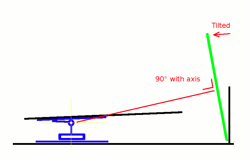
Modification 1
In 2008 it turned out that I could no longer rotate the cursor movement in Windows Vista by rotate 90°,
because the mouse I used was no longer supported by the Logitech driver.
Also in Ubuntu Linux, things were changed, and I was not able to set the 90° rotation.
So I was forced to replace the optical part with something that was small enough to mount
on the front end of the right foot pedal and was in the right direction.
I used my finger mouse for that. I used another mouse for the mouse buttons.
So now I had two separate mice in my foot mouse.
1. Optical part of the finger mouse.
2. Main part of the finger mouse.
3. Second mouse for the buttons of the left pedal.
My foot mouse worked again, but it was no longer wireless, the accuracy was much less,
and a double click was missing.
Modification 2
With the Logitech MX Air.
This seemed ideal to me, but it turned out to be unusable.
I attached my Logitech MX Air (air mouse) to the right pedal.
The MX Air is designed to hold in your hand and move it in the air.
It turned out, that Logitech has set the MX Air for that purpose to the optimal settings.
Very small movements are not well detected,
and the mouse went very quickly into standby, so it would take a little more
movement to get it out of standby.
That makes the MX Air not a good choice to use it with a footmouse
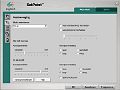
With the the Logitech driver (SetPoint 4.80) in Microsoft Windows, it is
possible to improve it, by setting the speed higher and the acceleration
lower. However, it is still not perfect.
Modification 3
With the Gyration Gyrotransport.
The Gyrotransport is only active when a button is pressed,
therefor I shortcut the button with a wire so it was always 'on'.
Because it was now always on, the battery didn't last a day.
So I used a LM317 Voltage Regulator to convert the 5 Volt of the
USB-bus to 1.5 Volt. I attached this mouse (without its case)
underneath the right pedal.
The quality of this mouse turned out to be too bad to be of use.
Every now and then it won't switch on, and the cursor often drifts away (every 5 minutes or so).
Also the cursor speed is very slow. And if I double the cursor speed in the operating system,
then my other mice are to fast.
Modification 4
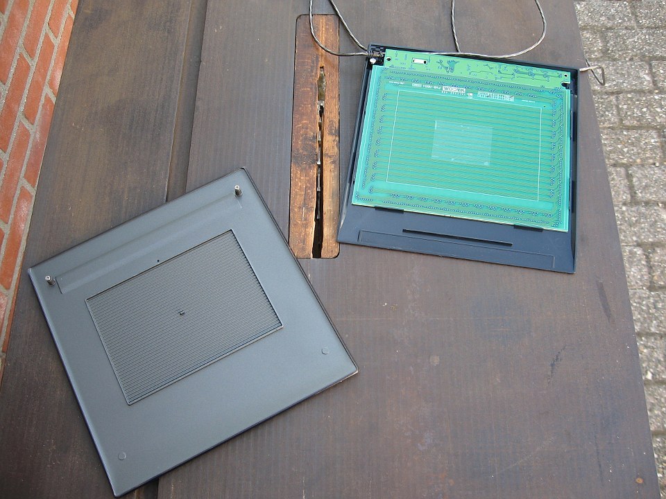
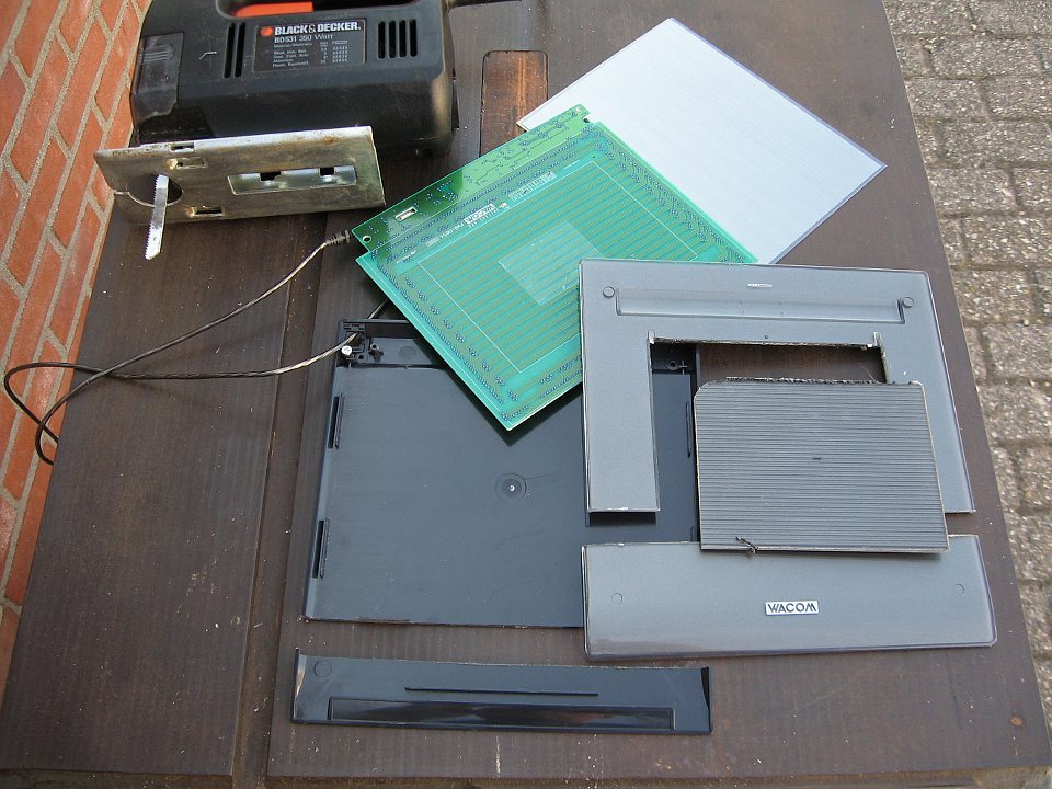
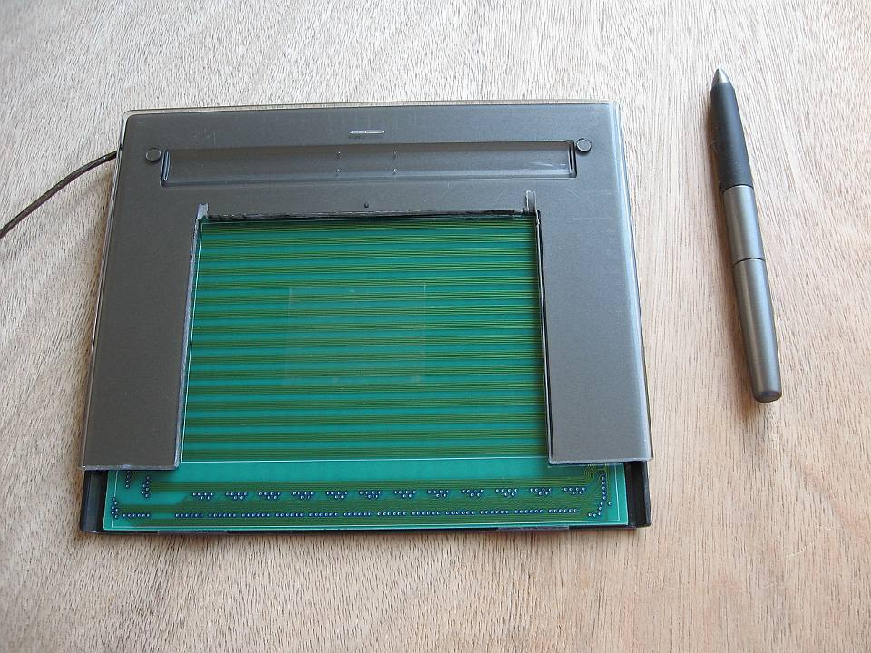
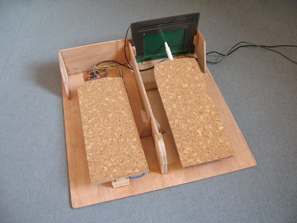
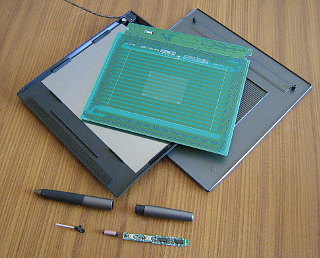
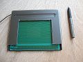
With a pen tablet.
I took my Wacom Volito2 apart, and then I could use it for my foot mouse.
To follow the movement of the right pedal, a concave shape would be required,
but the flat tablet without the housing turned out to have enough slack to follow the pedal movement.
2009
I made a second foot mouse for the pen-tablet.


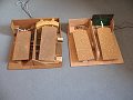

I used spruce plywood with a thickness of only 6 mm.
It was to reduce the weight of the footmouse.
But after all, it would have been better to use 10 mm (1 cm) plywood,
because that is more firm and easier.
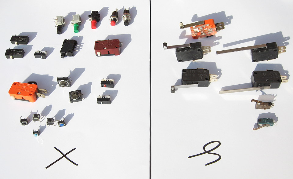
I used micro-switches for the mouse buttons.
That made it easy to double click a button, but keeping the button
pressed while dragging with the cursor turned out to be difficult.
So it would be better if I would replace the switches with micro-switches with a lever and roller.
Dimensions for DIY foot mouse:
Wood: 8 or 10 mm thick plywood.
Base plate: 45 x 45 cm.
Pedal: 32 x 13 cm.
Height of standing parts (the "walls"): 10 cm.
Height of ball bearing with door hinge: 4 cm (36 ... 50mm).
The height depends heavily on how much the right pedal needs to tilt to scan the whole active area of the tablet.
My foot is 27 cm long, and the length of my shoes is 31 cm.
For smaller feet, the whole foot mouse could be made smaller.
In the middle of the standing section a hole can be made.
This can be used as a handle to carry the foot mouse.
In 2012 I got cramps in my legs, because of my foot mouse.
I walk and move too little and my
tilted bed has also a bad
influence on the blood flow through my legs.
So I tried quinine:

inhibin® is a registered trademark of Meda Pharma B.V., The Netherlands.
This image of the box inhibin is not Public Domain.
The medicine inhibin® is for nocturnal muscle cramps. That is a medical
condition and I think that I had something else.
I had the impression that it helped somewhat.
However, some studies showed that the medicine hardly helps against
nocturnal muscle cramps and perhaps not at all.
Therefor, doctors are advised in 2020 to no longer prescribe this medicine.
My "Mattress with Motion" did help well
against leg cramps.
A low-salt diet did help even more.
2021
In 2021, the micro-switches (with a spring inside and a lever) of my first footmouse are still reliable,
but the push-buttons (with a metal dome membrane) of my second footmouse were not.
Rights: The photos and drawings on this page are made
by myself and are Public Domain, unless otherwise noted.
Last change to this page: January 2021